
solarFRAM
https://github.com/dragonlock2/kicadboards/tree/main/tests/solarFRAM https://github.com/dragonlock2/miscboards/tree/main/pic/solarFRAM
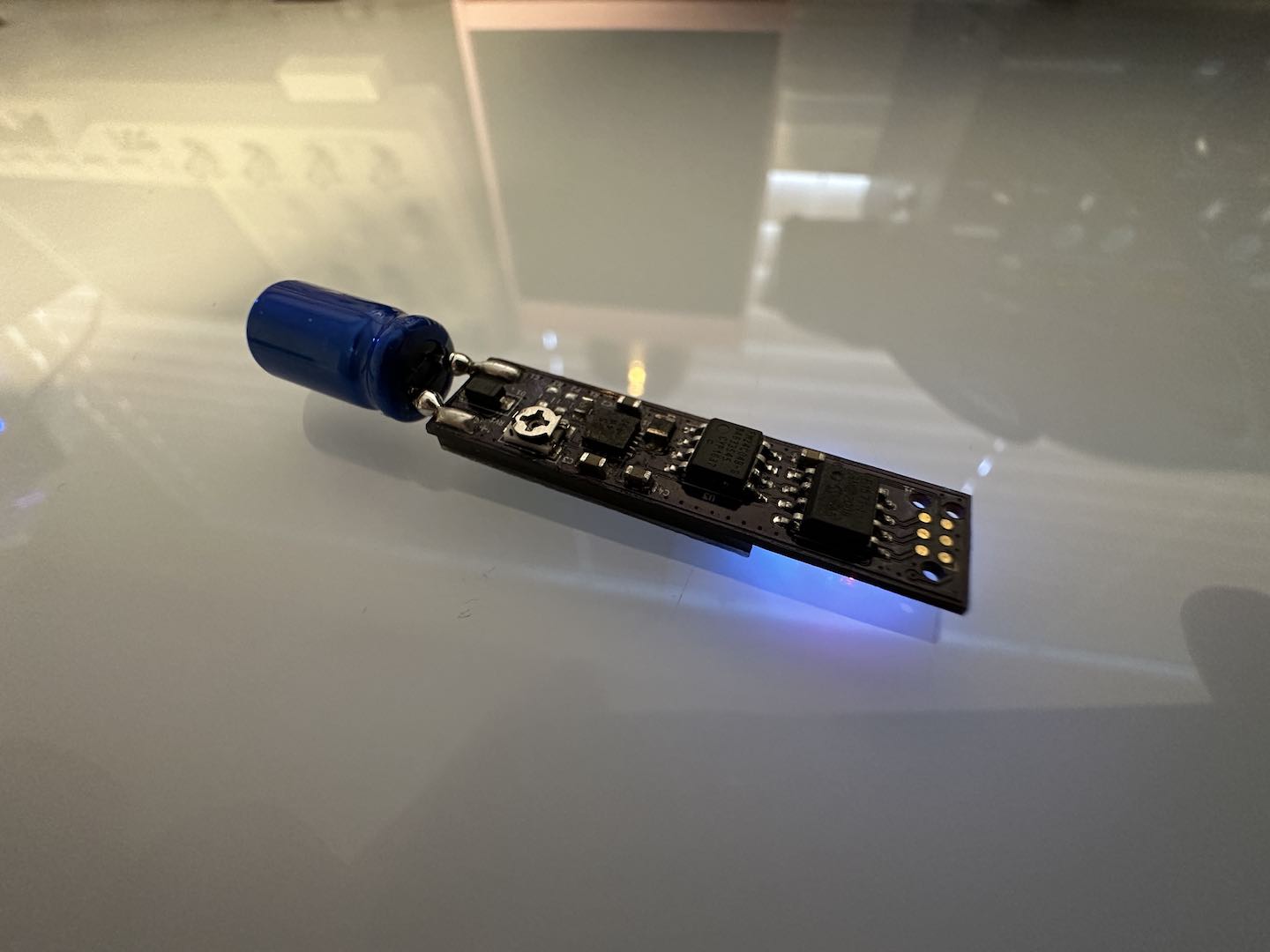
Since I bought a solar panel, low-end PIC, and FRAM for fun a long time ago, I decided to make a board to combine them all. Essentially, this board uses solar power to turn on a PIC which tests FRAM endurance until the capacitor depletes. If the capacitor doesn’t go out, this will probably outlast me.
To harness solar power, we simply pipe the output through a diode into a supercapacitor. It’s far from the most efficient method which would employ something like an MPPT, but one can only do so much with parts I had on hand. Since the solar panel output voltage was in the ~0.5V range, I needed a boost converter for which I had a TPS61201. I did some basic conservative calculations to set the UVLO and supercapacitor size in a way that would deliver enough energy into my circuit for at least a noticeable amount of time. One issue was that the output voltage was fixed at 3v3 but my FRAM needed 5V. Noting that the TPS61200 has an adjustable output, I correctly assumed that the TPS61201 is the same just with an internal divider. By adding an external potentiometer, I was able to force the TPS61201 to output 5V! The rest of the circuit was typical microcontroller stuff, not much to say there.
The software side was interesting as this was my first PIC project. Getting CMake set up was a pain and involved importing another repo since the process isn’t simple. Definitely sticking to AVR in the future. I ended up bitbanging I2C (and UART for debugging at some point). I also downclocked everything to keep the power draw low.
Overall, I’m happy with the project. My conservative calculations were pretty off and it doesn’t turn on as quickly or last as long as I’d hoped and only does so in sunlight or a bright flashlight, but it works! Perhaps I’ll try another solar powered project in the future.
Comments